The day has finally arrived i bought the kit car at Exeter kit car show 2010 .Only took me 18month to actually start the blogg. I went with a open view to which car i was going to buy and had narrowed it down to 3 companies. But there is no substitute than getting in the mix of it and having a chat with them and finding out more about there product. The GBS boys seemed so friendly and willing to help with any questions i had asked. so took the plunge and bought the 2345 package with twin cobra hoops and lowered floor in the powder coated finish.
While i was at the show i also bought a few other items. I had read a article in which kit car mag about DIY powder coating and looking at their product at the shown bought a kit of them at a very good price with 3 bags of powder chucked in for free. All i need now is a compressor to make the thing work off to machine mart for me then.
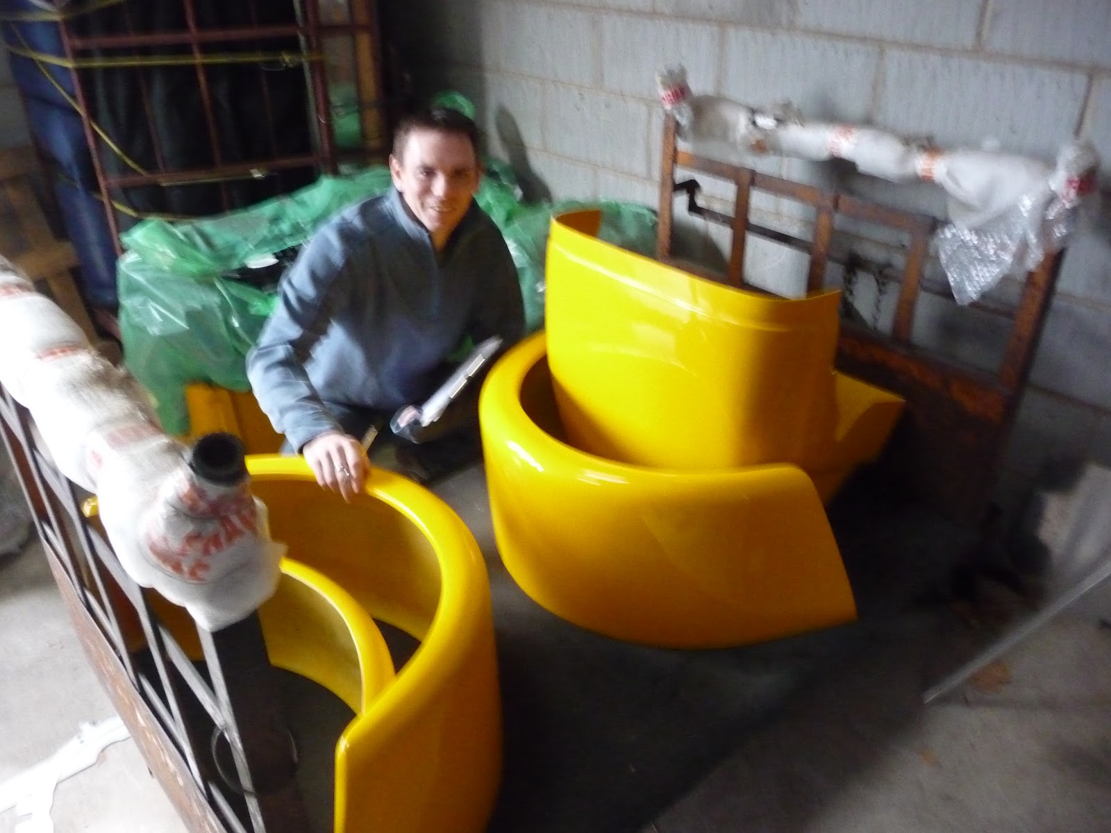
The kit on the trolley ready and awaiting tp load up into the long wheel base transit van. GBS bubble rapped all the body panels for me before loading up.

While i was making a work bench for the car and generally sorting out the garage a mate gave a 36inch LCD TV so up it goes, it would be rude not to, coupled up with a spare stereo knocking around and while i was at re directed the Virgin box into the garage. so tune and TV at the ready for some long nights in the garage.
THE COMPANY DEMONSTRATOR

The company demonstrator car was pulled out to take out for a quick blast again. keith was at the wheel and the fella can drive. The car handles really well on the tight twisty bits and then back into the factory entrance for a doughnut or two.
While out for a spin the GBS lads loaded up then van.
Another brew and then time to hit the road for the 3 hour trip back foot down unload and a few pints to celebrated the new arrival.
THE POP RIVETING BEGINS

I started with the back panel after reading a few blogs on the RHOC site marking the hole every 50mm and use a center punch to mark where you are drilling so the drill bit does not move, I would recommend spend the extra cash on good drill bits i bought some cheap ish one and they didn't last long. Once all holes are drilled clean all the holes up front and back by deburring them for a tight clean fit to the chassis,then sealing with the Alpha bonding agent from kit spares. this stuff get every where and is very strong and sticky so be warned.

Next was to fit and bond the driver/passenger side foot well panels. The steering column bush housing needs a slight mod with the hammer so the steering column lines up with the steering rack correctly otherwise the column with not sit in the bush correctly couple of bashes later and we are there.

The inside foot well panel was bent where the two panels meet to for a bit

Next it was time to fit the side panels lot more drilling filing and more bonding. the underneath has been drilled, but not yet pop riveted, this is to allow easier access for bolting up the engine mounts at a later date. I used a lot more clamps than this picture shown but forgot to take some photos of this part.

Time to start running in some brake line a new brake master cylinder was bought and mounted up front and a 4 port brake union with a mechanical brake light switch mounted. Next was to bend up a bit of 3/16 copper brake line with a male and female adapter on to connect to the brake light switch and goodridge hoses. A flaring kit is required for this process with a double flare for male connections and a single fore for female connections.Brake are pretty important for staying alive so make sure there are no score marks on the flares as these will leak brake fluid and all connections are tight but not over tight. If you don't make the final connection straight away make sure you tape up the end to stop crap getting in there.
I also ran in my hand brake cable in at the same time.

Brake lines where also fitted at the front using rubber P clips mounted every 150mm. I was originally going to pop rivet these in place but decided to use 4mm socket cap to mount these so i had to drill a 3.2mm hole and tap all the hole and screwed in. This was so the brake lines could easily renewed if ever required. let hope not

Next i bought the diff. this was bought from a scrap yard for £150 with a steering column and front up rights. Hours have been spent cleaning the diff up and a quick lick of primer and a spray of silver hammer-rite paint i think it has come up a treat. Before i installed the diff it was recommended that i take take the back plate of and do visible inspection to see if everything looked ok, just a top up of juices and all should be fine(well Let hope so)
The Diff is a 3.6 ratio with Lobro Cv joints.
The CV joint where in a ok condition but i decided to stripped these down and replace all 4 of them. While i was at it i cracked open the powder coating kit which has been sat there for 6 months and had a play at powder coating the drive shafts.

Now time to rebuild the drive shafts. 4 new CV joints have been sourced from J&R ebay shop for £18 each plus £5 postage. hopefully all should be smooth rolling in the future. The half shafts also got a good clean up but all has not been installed yet as i have not yet found a set of rear hubs suitable for disk brakes.
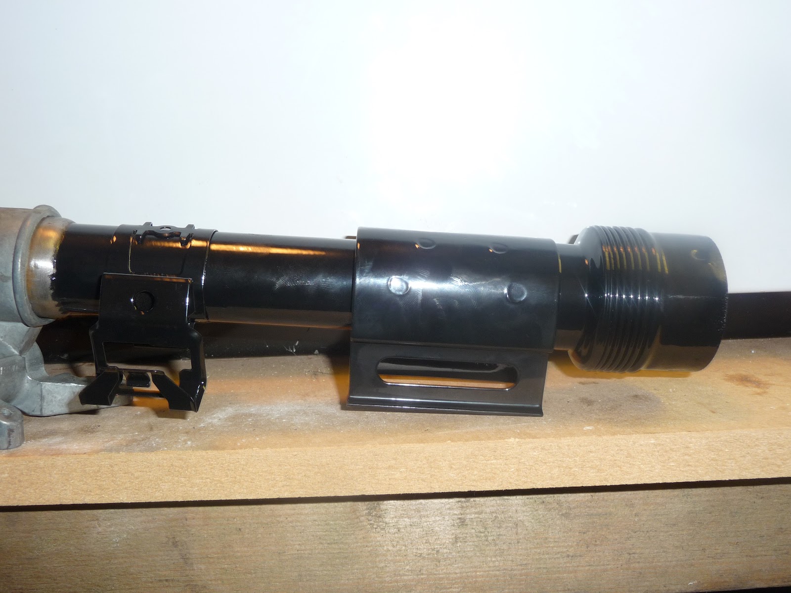
The steering column was sourced from Kit spares with the barrel still in place and no key. i wasn't sure how this would arrive with key/barrel or with a barrel that was not of any use. After a bit or research on this on the tinternet it was of my understanding this could be drilled out quite easily. (How wrong was i???)
The ignition barrel has to be in the first position,the best bet is to drill down into the barrel (but take your time as you can easily damage the internal mechanism if you go to far) so you can eventually turn it with a screw driver, Once in the first position you'll need to press in the release pin underneath the barrel,
On the other hand you could just buy a new one as i had to after i completely buggered up this process as i battered the barrel to death with a mallet trying to get it out. but i got it right the second time around with a bit more care taken. If you do go looking to source a upper steering column try and find one with a key or the barrel removed. This will be easier in the long run and probably cheaper in my case.

Just for a bit of fun i thought i would do the mounting bracket in a the blue to see what it looked like. i think it looks ok but this will be hidden and out of site. Everything now is in danger of getting powder coated.

Even the steering rack mounting brackets got the powder coating treatment. the bolts have now been changed to cap socket as i think the look a better finish.

The fire wall wall tabs where all bent forward and clamped in place and positioned roughly in place.
The scuttle panel needs bending at the edges to form a flat base where this sits on the chassis.. I achieved this by borrowing a sheet metal bending machine from a mate very use full bit of kit but not something that i could justify spending another £50 on as cost could easily soon mount up on extra bits.
I was planning on buying the GRP dash board in matching yellow from GBS. See what i mean don't really need it but Hey Ho. I have seen some good examples on the RHOC web site using the standard dash but how good does the GRP dash look. If using the GRP dash you don't need the outer dash panel so put this to one side. Now you have 2 options here you can cut the inner dash panel to suit or buy a pre cut panel from GBS. i opted for option 1 cut the panel. While at show i had a chat with Ben and he said you just need to mark the panel out about 25mm from the top all the way around the panel, and cut sounds simple and is. With tin snips at the ready and a file at hand this was a simple job to do and saves a bit of cash well if you don't count the additional cost of the GRP dash. The tabs on the inner dash where bent forwards and offered up to the scuttle and clamped in place before finally drilling. where any metal meets metal its advisable to use a small amount of bonding agent to help seal and stop panels vibrating against each other so small amount of sticky stuff was applied to each tab before finally pop riveting in place. when drilling the holes you need to get them a s close to edge a possible this will all be cover up with edging trim but be careful and take your time and all will be good.
Next it was time to order the dash this is was on a 2-3 waiting list but not the end of the world.

Next i sourced some rear hubs from Old Timbo a chap on RHOC forum. These hubs have been taken off a sierra 4x4 with rear disc just what i needed from aVery nice chap who said make him a offer so i did and then sends a message back saying take £15 off the original agreed price because one of the bearing needs replacing. very good deal all in for £45 with postage and arrived in 3 days so big thanks to Old Timbo.
The hubs arrive so out came the scrubbing brush again and started cleaning up the hubs ready for some paint or maybe some powder coating. I decided paint would be better in this case as i would have to strip the bearing out and replace them all if i was going to powder coat them. as it was i needed to replace one bearing which was a simple enough job re packed the other side with grease.
Before painting you need to replace the wheel studs for longer items due to the wheel off set required. so hammer at the ready a quick soak with WD40 and a couple off whacks out the pop and a simple mater of popining the new one in. i use a few washers over the studs and a nut to pull the stud tight to the flange.
Now i better get cracking with re building my drive shafts as i still not done them yet.


Right time for the dreaded rear panel. i read a few blogs from the RHOC web site for this.
The first thing to do is bend the tabs on the rear panel as using the same technique as the scuttle panels but taking your time. once this was done you have to do the same to the inner panel that hold the thin floppy bit that attachs to the rar panel. Then i bolted the roll bar stays to the thin floppy section and main rear panel to see if the holes all line up. But to no surprise it didn't so i to widen the holes to suite and had to pries the stay of the roll bar up with the finesse of a 2 x 2 timber as it seem to be pushing the rear panel down so it didn't sit very level and didn't look quite right.

I then formed the top section of the rear panel to internal rear quarter panels. the bolts at the back where only lose to let a bit of play and really just to see how the think sat on the car. The btabs in the corner need a bit of fine adjustment / trimming as when the rear panel was bent round the tabs where squashing up tight and pushing the top panel up so it was not sitting flush to the rear panel. after a an hour with the dremmel adjusting both side it all seem to settle down and looked a lot better
Then i bent the rear panel round and clamped it all together and then fitted the black tapole bead between the panel. you need to cut V shapes into the bead to bend it around the corners but not all the way to the edge and slotted it all in clamping it tight as you go.
after a lot of fiddling tweaking and tightening the rear stay bolts up and loosening the off it all seems there or ther abouts.
Then came the dreaded bit. drilling the holes. Firstly you need to mark the posistion of the hole i stuck with 50mm apart. i started in the midldle with a self tapper. then started with the corners.


 |
| Right a lot has happened over the last 9 months or so the arrival of my new daughter and a new job = no time to play with the kit car |

 |


 |
| My new toy |
 |
| I tried to convince the wife to sell her BMW but being selfish she wanted a 5 door car and not a 3 door hatch. dont see the problem myself. the only question is how long can i keep the focus st before she makes me sell it. |


 |
Finally managed to getting the engine, the type 9 gear box was bought for me for a farther's day present from my eldest daughter in 2012 but only just managed to get the thing cleaned up and sprayed with silver haammerite. the gear box require a larger clutch arm pin .The Clutch Arm Adjuster corrects geometry for right alignment for the Zetec standard clutch with the Type 9 gear box. Also use clutch release bearing. to mount the gear box dowels. these are are mount in the |


This comment has been removed by a blog administrator.
ReplyDelete